Page History
| Content layer | ||||||||||||||||||||||||||||||||||||||||||||||||||||||||||||||||||||||||||||||||||||||||||||||||||||||||||||||||||||||||||||||||||||||||||||||||||||||||||||||||||||||||||||||||||||||||||||||||||||||||||||||||||||||||||||||||||||||||||||||||||||||||||||||||
|---|---|---|---|---|---|---|---|---|---|---|---|---|---|---|---|---|---|---|---|---|---|---|---|---|---|---|---|---|---|---|---|---|---|---|---|---|---|---|---|---|---|---|---|---|---|---|---|---|---|---|---|---|---|---|---|---|---|---|---|---|---|---|---|---|---|---|---|---|---|---|---|---|---|---|---|---|---|---|---|---|---|---|---|---|---|---|---|---|---|---|---|---|---|---|---|---|---|---|---|---|---|---|---|---|---|---|---|---|---|---|---|---|---|---|---|---|---|---|---|---|---|---|---|---|---|---|---|---|---|---|---|---|---|---|---|---|---|---|---|---|---|---|---|---|---|---|---|---|---|---|---|---|---|---|---|---|---|---|---|---|---|---|---|---|---|---|---|---|---|---|---|---|---|---|---|---|---|---|---|---|---|---|---|---|---|---|---|---|---|---|---|---|---|---|---|---|---|---|---|---|---|---|---|---|---|---|---|---|---|---|---|---|---|---|---|---|---|---|---|---|---|---|---|---|---|---|---|---|---|---|---|---|---|---|---|---|---|---|---|---|---|---|---|---|---|---|---|---|---|---|---|---|---|---|---|---|
| ||||||||||||||||||||||||||||||||||||||||||||||||||||||||||||||||||||||||||||||||||||||||||||||||||||||||||||||||||||||||||||||||||||||||||||||||||||||||||||||||||||||||||||||||||||||||||||||||||||||||||||||||||||||||||||||||||||||||||||||||||||||||||||||||
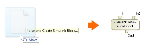
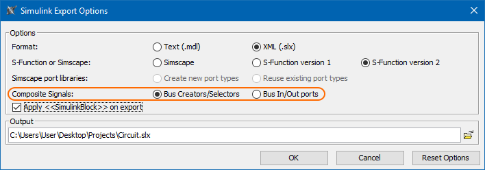
Simulink Composite Signals exportYou can now select how to export Proxy Port or Interface Block with multiple Flow Properties (composite signals): as bus Creators/Selectors or as bus In/Out ports.
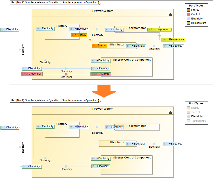
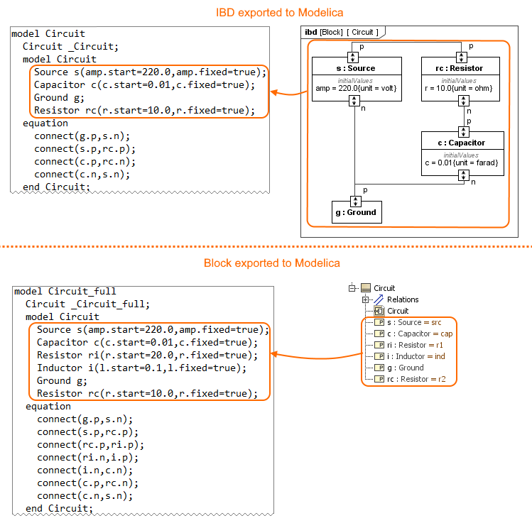
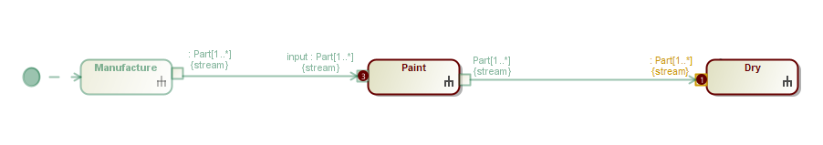
Learn more about Simulink export >> IBD-based Selective Modelica ExportYou can now use the Internal Block Diagram to select what to export to Modelica. Only use the Internal Block Diagram to select what to export to Modelica. Only parts, ports, and connectors appearing in this diagram are exported, rather than the entire model. See whole vs partial export comparison in the image below.
The difference between whole (exporting Block) and partial (exporting IBD) export to the Modelica file.Content block |
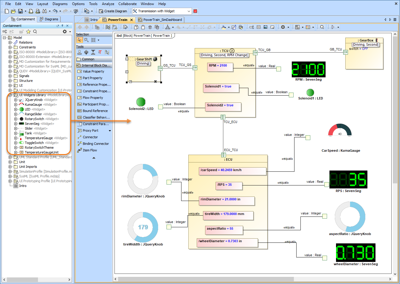
Anchor | sim | sim | SimulationHTML Widgets in IBD DiagramsCameo Simulation Toolkit introduces a new powerful mechanism to integrate any third-party interactive HTML components (widgets) into SysML diagrams for simulation. A set of predefined widgets is available in UI Widgets Library. You can drag and drop widgets to IBD diagrams and connect them to appropriate value properties to provide inputs or read outputs. If you have basic HTML and JavaScript skills, you can manually create new custom widgets and integrate them into simulation. Please note that the free Web Server for Cameo Simulation Tookit plugin is required for this functionality.
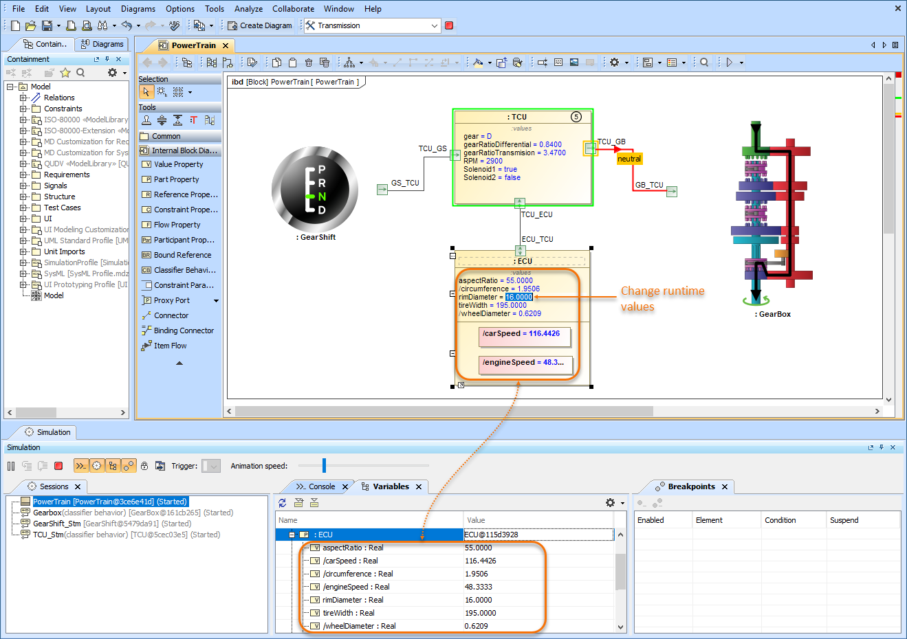
The example of using widgets from UI Widgets Library in an Internal Block Definition Diagram.Learn more about integrating widgets for simulation >> Displaying and Changing Runtime Values in DiagramsWIth Cameo Simulation Toolkit 20.0 monitoring and manipulating simulation information has never been easier. Now you can display runtime values of Parts in all diagrams based on a Composite Structure Diagram as shown in the figure below. But that is not all, you can also modify runtime values directly in a diagram the same way you do it in the Simulation window.
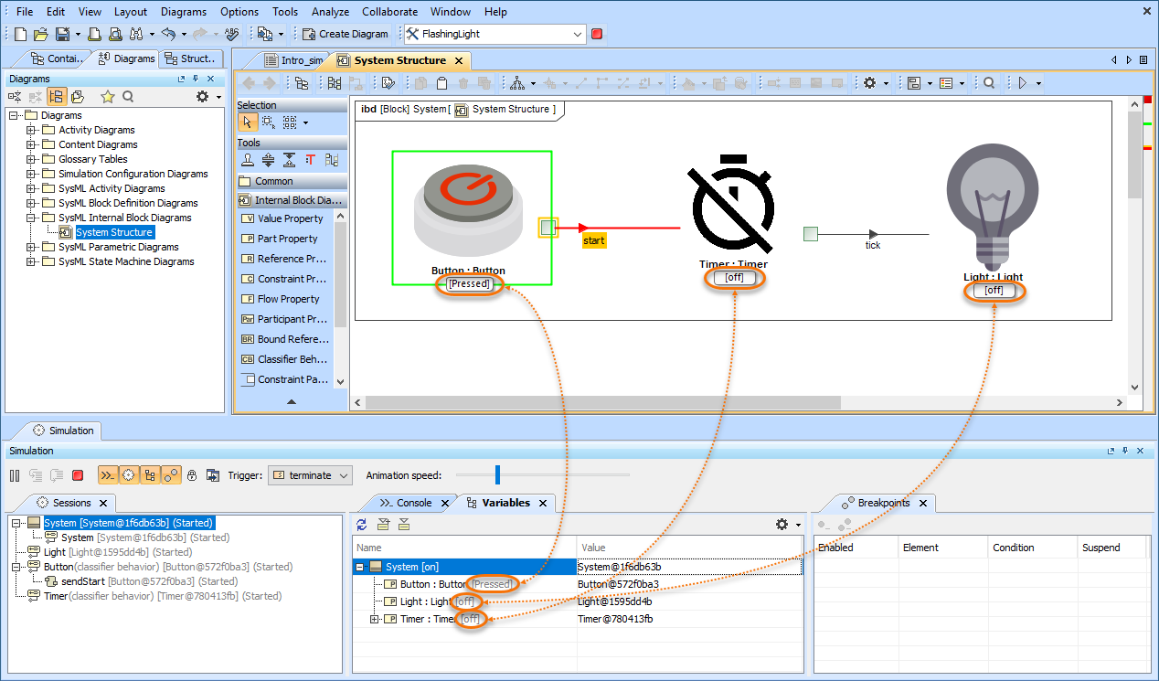
This sample model demonstrates how you can view and change runtime values of Parts directly in an Internal Block Definition Diagram.Displaying Active State in DiagramsNow diagrams based on a Composite Structure Diagram display the active States of Parts when simulating a model. Active states are shown on the bottom of Part shapes the same way they are displayed in the Variables pane of the Simulation window. This new feature improves the readability of simulation information because you no longer need the Simulation window to see how active States change when executing your model.
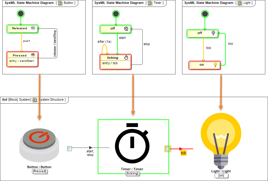
In this Internal Block Definition Diagram, you can see that active States are displayed both in the Simulation window and on the shapes of initialized Parts.Displaying Active State ImagesMake your model simulation look more illustrative and vivid by displaying active State images on Part shapes. You can do that by assigning an Image Switcher to the Simulation Configuration from which you execute your model or by applying an image to a State. When states change during simulation, state images change as well as displayed in the following figure.
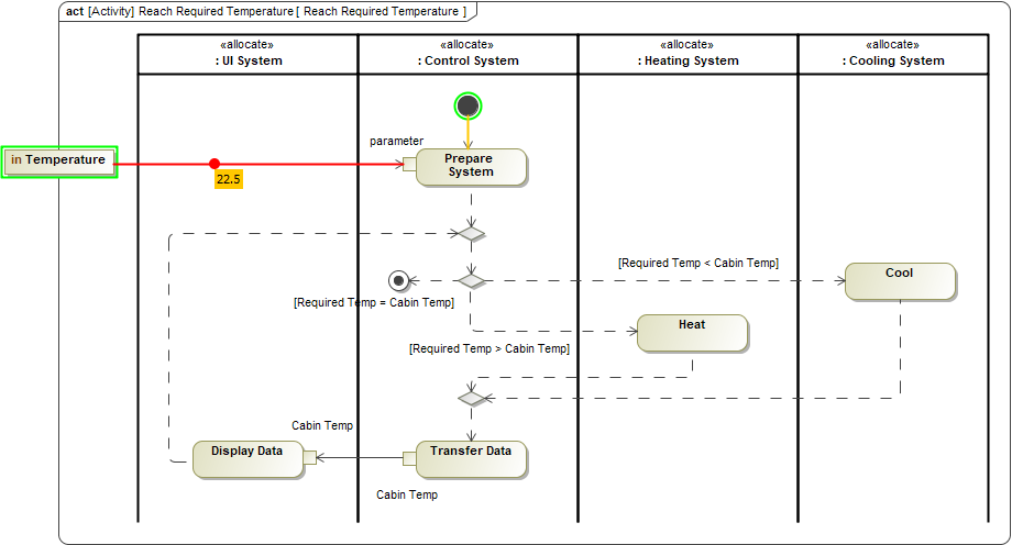
Here you can see how active State images are displayed when simulating a model.Displaying Flowing InformationCameo Simulation Toolkit 20.0 allows you to see what information is flowing via paths that are animated during model execution. In Activity Diagrams, the flowing item is displayed as a bubble with a label showing the item name. In diagrams based on a Composite Structure Diagram, a moving triangle is shown on an animated path as illustrated below.
The temperature value flowing in an Activity Diagram.
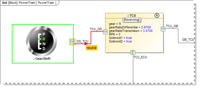
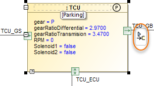
In this Internal Block Definition Diagram, you can see the neutral signal flowing from the GearShift to the Transmission Control Unit (TCU).Sending a Trigger in DiagramsNow sending a trigger during model simulation is even more convenient because you can do it right from a diagram without using the Simulation window. You can send a trigger directly from a Part shape in all diagrams based on a Composite Structure Diagram. When it is possible to send a trigger, a special button is displayed on a Part shape after selecting it.
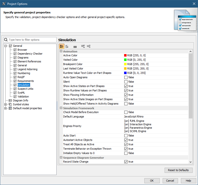
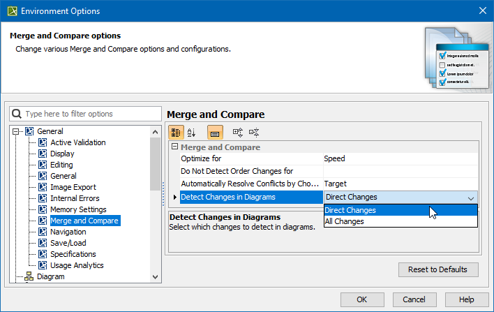
Simply click the highlighted button to send a trigger from a Part. If it is possible to send several triggers, the trigger list will be displayed for you to select from.Reorganized Simulation OptionsAll Simulation options have been moved from Environment Options to Project Options for better user convenience, as it allows customizing simulation to fit a particular project. In addition, all simulation settings will be exchanged among users who collaborate on a server. Furthermore, most of the Simulation Configuration options are duplicated in Project Options now, so you can specify default values for execution without using Simulation Configuration.
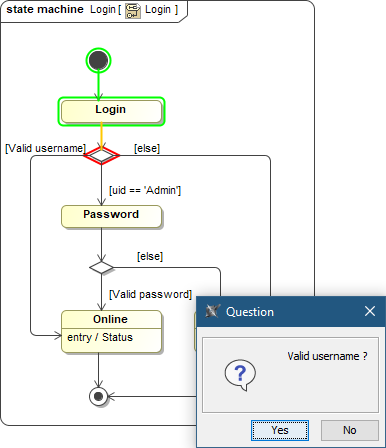
As you can see in this figure, all simulation options are now accessible in the Project Options dialog.Animation Delay LogicAnimation delay affects only visible diagrams now. All closed diagrams and models run at full speed with no delays. Interactive Guard Evaluation for STM and Sequence DiagramsThe guard conditions on transitions expressed in natural language cannot be evaluated, so the question dialog will be shown for you to choose. This behavior is consistent with decision nodes in Activity Diagrams.
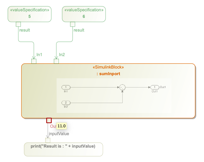
When simulating this State Machine Diagram, a user is asked to choose whether a user name is valid or not.Simulink Co-Simulation in Activity DiagramsA Simulink *.slx file can be dropped into an Activity Diagram to create «SimulinkBlock» Activity and Call Behavior Action for it. If the file is attached to your project or stored in the project directory, Cameo Simulation Toolkit will be able to execute it with given input values and provide outputs to the action output pins.
In this Activity Diagram, a «SimulinkBlock» action has been created from a Simulink *.slx file.OtherIt allows leaving a project open for the next simulation if multiple property files are used in the simulation command. 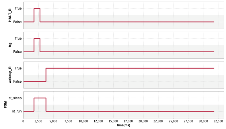 A new Record Time option is added into CSV export configuration to be able to turn off the timestamp column when it is not needed, e.g., when recording Trade Study or Monte Carlo iterations.  Content block |
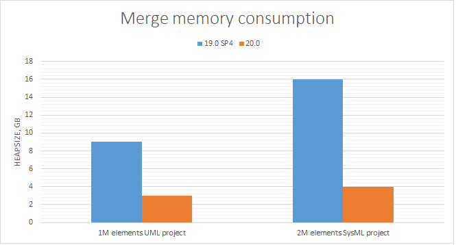
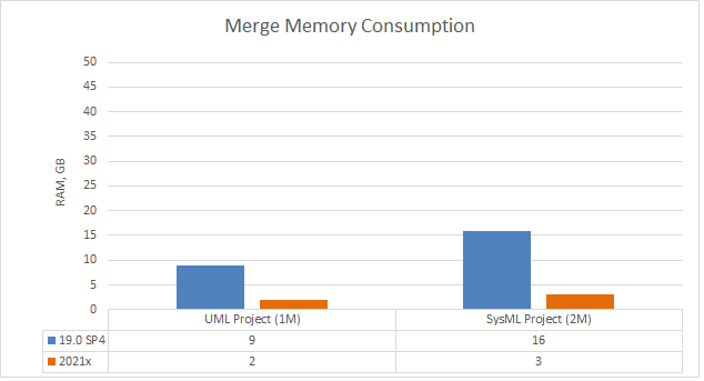
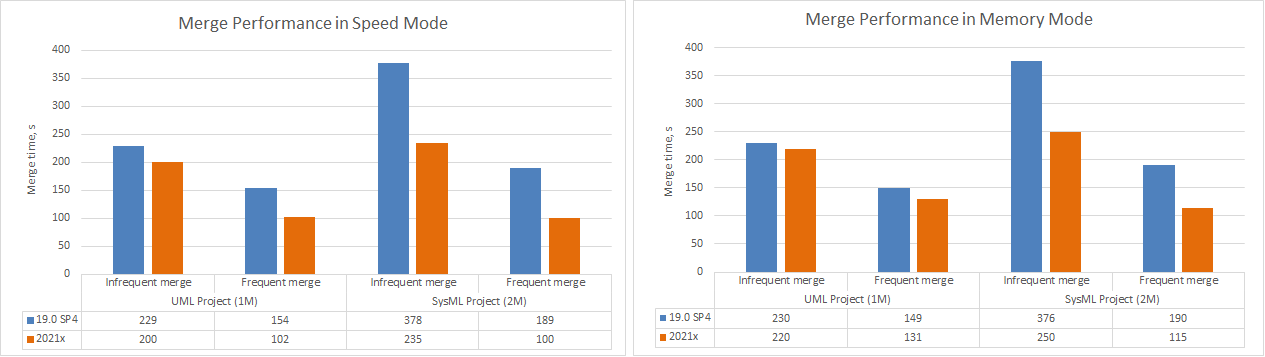
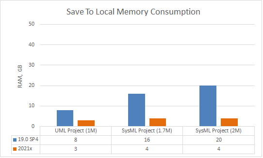
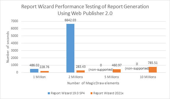
Anchor | Performance | Performance | Performance ImprovementsProject Merge ImprovementsProject Merge has undergone considerable performance improvements. Modeling tool version 20.0 requires 3-4 times less memory to successfully merge two server project branches compared to 19.0 SP4.
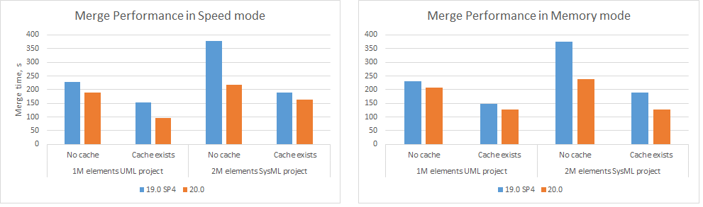
A chart comparing merge memory consumption in different modeling tool versions.Furthermore, the merge speed has increased by 20-70% in 20.0 compared to 19.0 SP4.
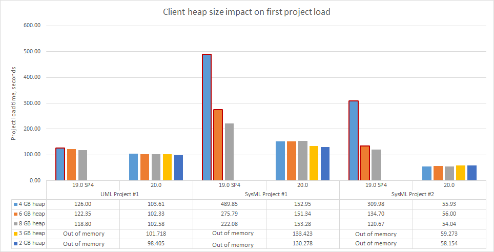
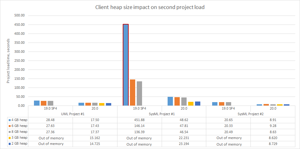
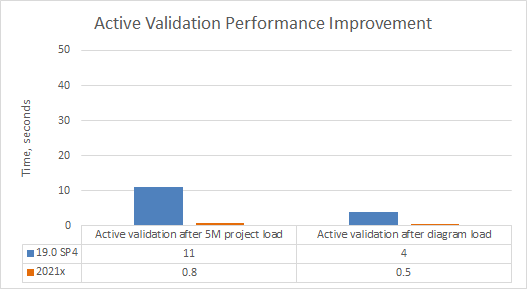
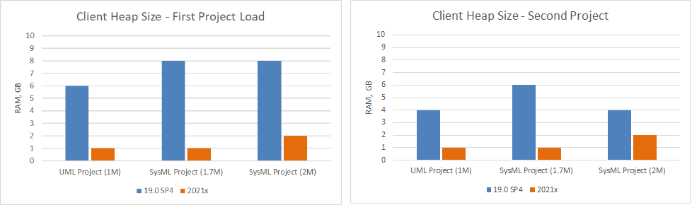
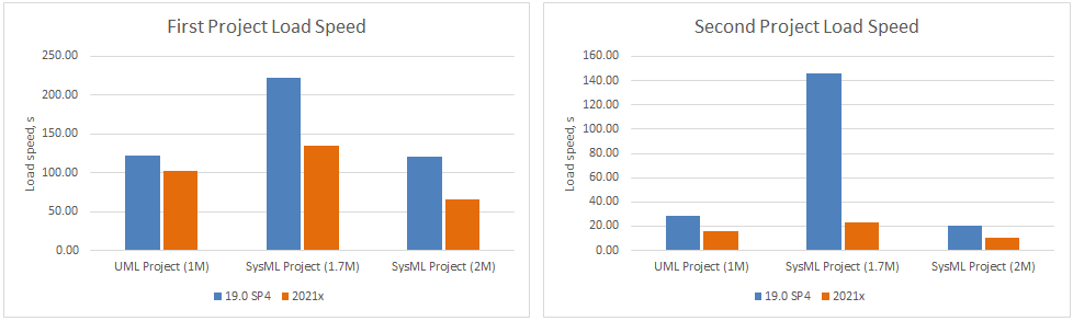
Charts comparing merge performance in speed and memory modes.TWC Project Load Memory and Speed ImprovementsProject load memory and speed improvements have been implemented for Teamwork Cloud. The modeling tool now requires only 2GB of heap to load a project (first and second time) when working with TWC projects compared to 8GB in 19.0 SP4. Additionally, as a result of the UML metamodel changes mostly, SysML projects are now opened 2-3 times faster. N.B Received results cover the project load only, excluding validation, diagramming, and further modeling tool feature usage. N.B A red border on a bar chart in the image below indicates a low memory occurrence during testing.
Charts comparing load memory and speed improvements between different modeling tool versions.
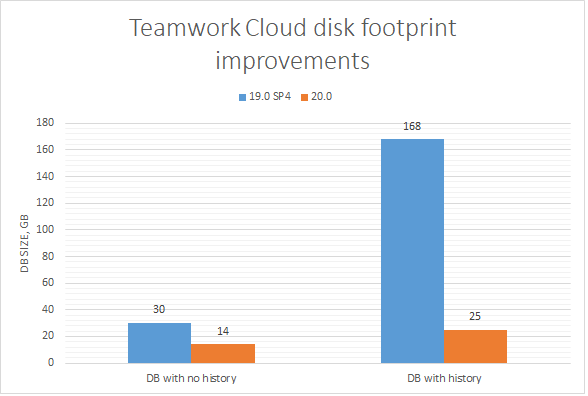
TWC Disk Footprint ImprovementsMajor TWC disk footprint-related changes are presented in this release. TWC 20.0 requires twice as less disk space for the same amount of projects with no history compared to TWC 19.0 SP4. In addition to this achievement, the disk size growth is cut nearly 5 times in TWC 20.0 compared to TWC 19.0 SP4 for those projects users work actively on.
A chart comparing TWC disk footprint between different modeling tool version
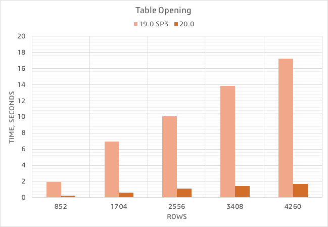
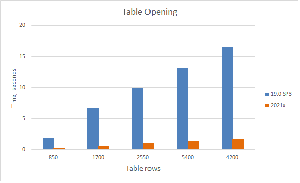
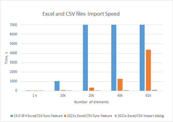
Partial Data Loading in TablesExperience enhanced table loading and scrolling performance! Thanks to the newly-introduced Load Partial mode, data is now loaded in only visible rows, meaning that there is no need to wait until data is calculated in the entire table. What is more, fast scrolling has improved – it is now considerably smoother.
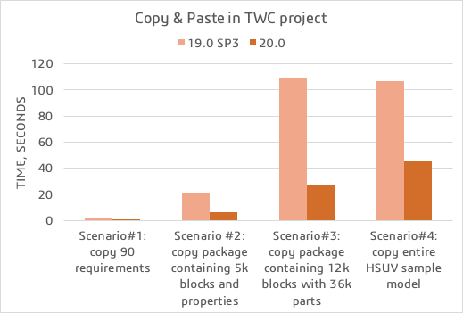
A chart comparing the opening time of Requirement Table having 7 standard columns with a different number of requirements.Learn more about partial loading in tables >> Enhanced Copying/Pasting Operation SpeedRecent modeling tool performance improvements have led to an increase in the copying/pasting operation speed. Now you can copy and paste data noticeably faster for maximized productivity.
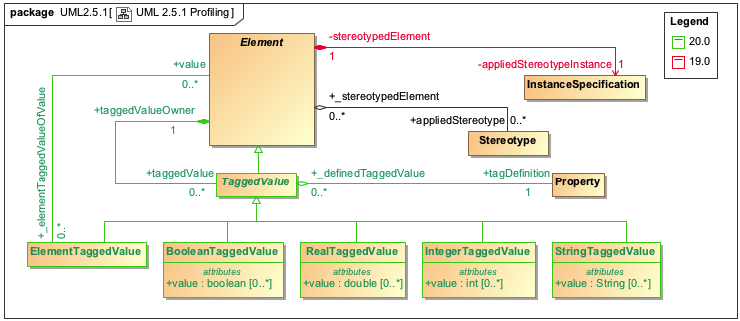
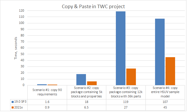
A chart comparing the copy&paste operation time in various scenarios.Profiling Changes in the UML 2.5.1 MetamodelSignificant changes have been implemented to the UML metamodel for performance reasons. The InstanceSpecifications, Slots, and ValueSpecifications are no longer used to store profiling data. Instead, new model element types and properties are introduced while some have been removed (see the diagram below).
Profiling changes in the UML metamodel.As shown in the figure above, Element references the TaggedValue that is used to specify the Boolean, Integer, Real, String, or Element values of the applied stereotype properties. This approach uses fewer model elements to store profiling data, which leads to a decrease in the total number of elements in SysML and UAF projects by 40-80%. N.B Expressions based on the previously implemented profiling data storing metamodel no longer work, meaning that they have to be updated manually.
| ||||||||||||||||||||||||||||||||||||||||||||||||||||||||||||||||||||||||||||||||||||||||||||||||||||||||||||||||||||||||||||||||||||||||||||||||||||||||||||||||||||||||||||||||||||||||||||||||||||||||||||||||||||||||||||||||||||||||||||||||||||||||