On this page
Description
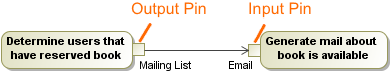
A Pin represents a connection point for the input and output values of an action. There is one input Pin for each input parameter, and one output pin for each output parameter.
Using MagicDraw, you can create the following types of Pins:
- Input Pin. An input pin is a pin that holds input values to be consumed by an action.
- Output Pin.
- Value Pin.
- Action Input Pin.
- When a new action is created that must have mandatory Pins, they are automatically added to that action on the diagram pane, as well as in the Containment tree.
- As of MagicDraw 17.0.4 version, the Pins Displaying validation suite has been introduced. It includes the Action Containing Hidden Pins validation rule that detects all hidden pins for the concrete action symbol.
- When deleting the last Pin symbol from the diagram, the Pin element is deleted from the project. This is valid when the Display All Pins in Diagrams option value is true.
- For a send signal action, a Pin is created, but the symbol of the Pin is not represented on the diagram pane.
- You can navigate to the associated parameter from the Pin shortcut menu. From the Pin shortcut menu, select Go To and choose a parameter.
You can format the pin symbol properties in the Symbol Properties dialog.
You can specify pin properties in the pin Specification window. In the Specification window, you can find the description of each property, which are located in the description area of the Specification window.
Assigning Pins
To assign Pins for an action on the diagram pane
- In the activity diagram, draw an action.
- In the activity diagram palette, select a Pin you want to create.
- On the diagram pane, click the action. The Pin for this action is created.
To assign Pins for an action in the action Specification window
- In the action Specification window, in Pins property group, select one of the following:
- Input Pin. Select Argument, and, in the property specification cell, click the Add button. Select one of the preferred pins from the list.
- Output Pin. Select Result, and in the property specification cell, click the Add button.
- In the opened Pin Specification window, type the Pin name.
- Click Close or Back to return to the action Specification window.
Specifying Pin type
After the Pin is assigned to an action, you can specify it's type. Use one of the following way:
To specify Pin type by using the Specify Type button
- Select the Pin shape.
- Click
 on the smart manipulator toolbar.
 - Do one of the following:
- Select an existing element from the Select Type menu.
- Create new type:
a. Type a name.
b. Press Enter.
c. In the Create <type name> As dialog, select element kind.
The type is specified for a Pin.
To specify Pin type by using the Specification window
- Right-click the Pin and select the Specification command.
- In the Specification window, select the Type property value cell.
- Do one of the following:
- Select an existing element from the list.
- Click and in the Select Element dialog do the following:
- Select an existing elements from the Tree or List tab.
- create new element by switching on the Creation Mode and clicking the Create button. - Click Close.
The type is specified for a Pin.
Displaying Pins
To display Pins on shapes
- On the diagram pane, select any number of shapes on which you want to display Pins.
- Open the Select Pins dialog by performing one of the following steps:
- From the shortcut menu, select Display > Display Pins.
- On the diagram toolbar, click and select Display Pins.
 In the dialog, select the Pins you want to display.
In the Layout options area, specify the Pins' layout on the shape:
- Top/Bottom - displays Pins on the shape from its top to bottom.
- Left/Right - displays Pins on the shape from its left to right.- When you are finished, click OK.
If you want all Pins to be displayed automatically when creating a new Activity diagram, go to Options > Project on the main menu, and set the Display All Pins in Diagrams option to true.
If you have an element displayed as an image, you can connect a Pin to that element with no gaps.
Showing Pin's type
To show the Pin’s type, perform one of the following steps
- From the Pin shortcut menu, select Show Type.
- In the Pin Symbol Properties dialog, set the Show Type property to true.
Converting a Pin
To convert an input Pin to an output Pin and vice versa
- From the Pin shortcut menu, select Refactor > Convert To.
- From the opened list, select one of the following:
- Input Pin (Output Pin)
- Action Input Pin
- Value Pin
To convert a Pin to an object node
- From the Pin shortcut menu, select Refactor > Convert To.
- From the opened list, select Object Node.
Navigating from a Pin to the associated parameter
To navigate from a Pin to the associated parameter
- From the Pin shortcut menu, select Go To, and choose a parameter.
Related pages