Overview
A Deployment diagram falls under the structural diagramming family. It focuses on showing the physical layout of various hardware components (Nodes), e.g. CPU, a database server, and an application server that compose a system as well as the distribution of executable programs (software components) on hardware. For instance, to describe a website, the Deployment diagram would show what hardware components exist, what software components run, and how the different pieces are interconnected. Deployment diagrams are crucial when dealing with distributed systems.
As of MagicDraw 17.0.1, the Deployment diagram (or the Component diagram) replaces the Implementation diagram, which is no longer supported in UML standard. An Implementation diagram created with earlier versions of MagicDraw, now opens as
- Deployment diagram, if Nodes were used in the Implementation diagram
- Component diagram, if Nodes were not used in the Implementation diagram
Customized diagrams that were based on the Implementation diagram are now based on the Component diagram.
Purpose
Using a Deployment diagram, you can show the actual computers and devices (Nodes), along with the connections they have to each other, thus specifying a system topology. Inside the Nodes, executable Components and objects are located in a way that it shows where the software units are residing and on which Nodes they are executed. You may also show dependencies between Components.
Usage
A Deployment diagram can be used to:
- show the structure of the run-time system
- capture the hardware that is going to be used to implement the system and links between different hardware items
- model physical hardware elements and the communication paths between them
- plan the system architecture
- document the deployment of software components or nodes.
Summary
Deployment diagrams are valuable because they can be:
- used to model the hardware platform for a system
- used to identify hardware capabilities that have an impact on the performance planning and software configuration.
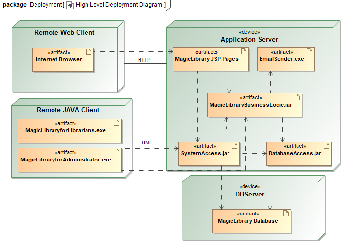
Example of a Deployment diagram
Related pages