The purpose of Whitebox ICD Table is to show how Part Properties are connected via ports/interfaces. This table collects all parts of the context element. Those parts are connected through the ports/interfaces using Connectors. You can visually identify what kind of ports/interfaces (Port A and Port B) and flows (Item Flow) are used to connects two Part Properties (Part A and Part B).
In the row 1 of the following figure, the Controller Part Property sends the control Signal to the Boiler Part Property through the ports b and c. The Controller receives the Status signal from the Boiler through the Ports c and b. In the row 2, the Part Controller sends the flow Elec Power to the Part Boiler through the Ports bp and p in. Learn how to create and work in the Interface Control Documents >>
 An example of Whitebox ICD Table.
In the created table, a row represents the Connector and the columns represent features of that Connector. You can add or remove column
Use the Show Parts dialog to filter connectors in the table.
To choose which connectors should be displayed or hidden
- In the Whitebox ICD Table toolbar, click Show Parts.
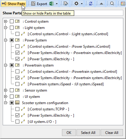
In the Show Parts dialog,select the connectors you want to hire or display.
Click OK.
If the part is in a partially selected state, clicking it selects all the connectors under that part. If the part is in fully selected state, clicking it cancels all the connector selections.
A Whitebox ICD Table consists of the following columns.
| Column name | Description |
|---|---|
| # | A row number. |
| Part A | Displays a Part that is connected with Part B. |
| Port A | Displays a Port that is connected with Port B. |
| Port A Features | Displays all the properties of the Port A. |
| Item Flow | Displays the flow kind and its direction which flows through the Connector between two Parts (Part A and Part B). |
| Port B | Displays a Port that is connected with Port A. |
| Port B Features | Displays all the properties of the Port B. |
| Part B | Displays a Part that is connected with Part A. |