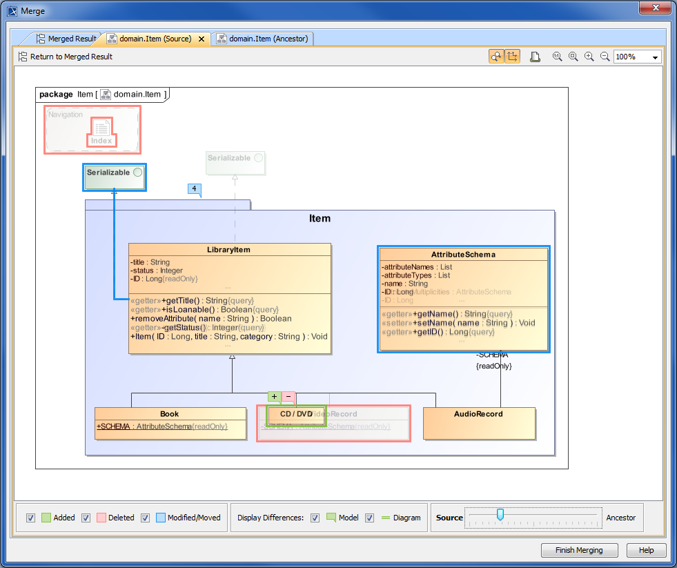
The different diagram versions are displayed in separate Difference Viewer tabs in the Merge window next to the Merged Result tree (see the following figure).
To open diagram difference viewers of a modified diagram
- Double-click the modified diagram in the Merged Result tree.
One, two or three new tabs open in the Merge window. In 3-way merge, the ancestor's tab is opened by default, the source's tab is opened, if changes have been detected in the source, and the target's tab is opened, if changes have been detected in the target. In 2-way merge, the target tab is opened by default. If a diagram is only available in source, only the source tab opens in the difference viewer .
All the diagram difference viewers are used to display the following changes:
- One or more symbols were moved or modified on the diagram.
- A new symbol was added to the diagram.
- A symbol was deleted from the diagram.
- The number of inner model elements has changed.
- A model element has been modified.
Be advised that symbols with property value changes that actually have no effect on their appearance are highlighted in a diagram difference viewer as well. For example, changing the Show Stereotypes property value in the Symbol Properties dialog of a class makes the class symbol highlighted as changed in a diagram difference viewer.
As you can see in the following figure, all these changes are marked by color coded lines and flags allowing the quick distinguishing between different types of changes. Numbers on flags indicate the number of changes made to that element. Clicking a flag switches to the Merged Result tab and selects the flagged element in the Merged Result tree.
The colors of lines and flags correspond to the color system explained in the difference legend:
- Blue flags indicate the number of modification/movement changes made to the element, blue lines represent modified/moved relations, and blue borders around symbols mark modified/moved elements in the diagram.
- Green flags indicate the number of addition changes made to the element, green lines represent added relations, and green borders around symbols mark added elements in the diagram.
- Red flags indicate the number of deletion changes made to the element, red lines represent deleted relations, and red borders around symbols mark deleted elements in the diagram.

You can customize the types of changes you want to be displayed in the difference viewer by using filtering options available in the legend. Simply select or clear selection from the appropriate check boxes and view the differences that are relevant to you.
![]()
If you would like to see the diagram version from other project version without switching between tabs, use the slider available at the bottom of the Difference Viewer. Moving the slider makes the current diagram symbols to fade, and the symbols from another diagram version start appearing. When the slider is set to the middle position, different symbols from both diagram.

You can manage the content of a diagram difference viewer using the toolbar that is located above it.
![]()
See the button descriptions in the following table.
Button | Tooltip text | Description |
Return to Merged Result | Click to open the Merged Result tree with the appropriate diagram selected within. | |
| Synchronize Zooming | Click to turn on or off the zooming synchronization in all difference viewers of the same diagram. |
| Synchronize Scrolling | Click to turn on or off scrolling synchronization in all difference viewers of the same diagram. |
| Print Diagram | Click the button to print a diagram. The diagram will be printed with highlighted areas on it, if the highlighting of the diagram changes is turned on. | |
 | Zooming | Use the buttons to control the diagram size. |
- Analyzing and managing merge results
- Getting merge summary information and changes legend
- Understanding content of the Merged Result tree
- Inspecting element property changes in the Specification panel
- Inspecting changes in the Change details panel
- Displaying and navigating through changes
- Quickly navigating through conflicting changes
- Accepting and rejecting changes
- Generating a differences report
