Page History
| Content layer | |||||||||||||||||||||||||||||||||||||||||||||||||||||||||||||||||||||||||||||||||||||||||||||||||||||||||||||||||||||||||||||||||||||||||||||||||||||||||
|---|---|---|---|---|---|---|---|---|---|---|---|---|---|---|---|---|---|---|---|---|---|---|---|---|---|---|---|---|---|---|---|---|---|---|---|---|---|---|---|---|---|---|---|---|---|---|---|---|---|---|---|---|---|---|---|---|---|---|---|---|---|---|---|---|---|---|---|---|---|---|---|---|---|---|---|---|---|---|---|---|---|---|---|---|---|---|---|---|---|---|---|---|---|---|---|---|---|---|---|---|---|---|---|---|---|---|---|---|---|---|---|---|---|---|---|---|---|---|---|---|---|---|---|---|---|---|---|---|---|---|---|---|---|---|---|---|---|---|---|---|---|---|---|---|---|---|---|---|---|---|---|---|---|
| |||||||||||||||||||||||||||||||||||||||||||||||||||||||||||||||||||||||||||||||||||||||||||||||||||||||||||||||||||||||||||||||||||||||||||||||||||||||||
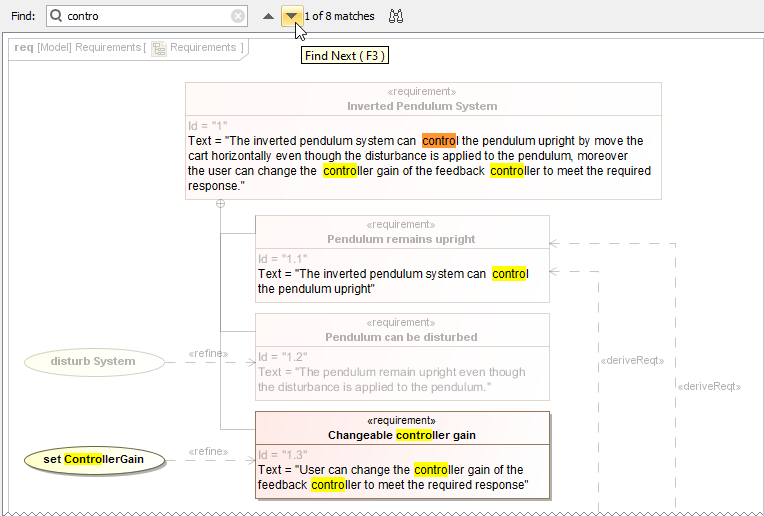
Cameo Systems Modeler 19Modeler 19.0 provides the ability to search for informationtextual information in all types of diagrams, including tables, matrices and maps. Open the search bar by clicking press Ctrl+F. Use this feature to find the desired text displayed in a large diagram and quickly navigate the search results . After typing the search phrase, the diagram scrolls to the first match (highlighted in orange), as shown below. Diagram symbols that do not contain your search phrase are shaded to emphasize the information you want to find.
How to use the Find feature in diagrams and navigate the search results.Learn more about searching in diagrams >>
Legends have been improved to allow a wider range of usage options. Now you can:
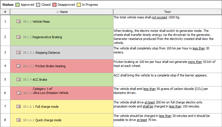
In this example, a legend is used to adorn Requirement table cells by Requirement status.Learn more about creating and using Legends >>
All new SysML projects use:
Learn more about model libraries >>
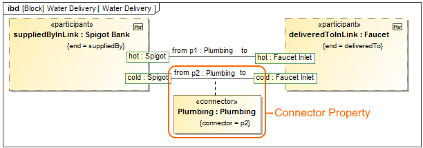
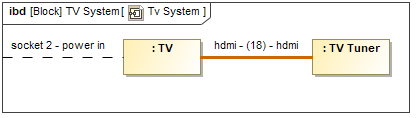
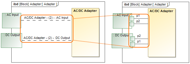
You will be able tocan now represent Association Block usages in the Internal Block Diagrams. Simply drag the Association Block from the model onto a Connector to set it as its type and automatically create a Connector Property symbol with a dashed line attached to the Connector. The Plumbing Connector Property is created after dragging the Plumbing Association Block on the p2 Connector.Learn more about Connector Property >>
The implied Connectors functionality is improved as follows:
Learn more about Implied Connectors >>
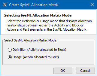
When creating a new SysML Allocation Matrix, you can choose Definition or Usage mode. Accordingly, these modes display Allocate relationships either between Activities and Blocks or Actions and Part Properties. By default, the Create SysML Allocation Matrix dialog (see the figure below) appears each time you create a new SysML Allocation Matrix in SysML projects. Differently, when creating a new SysML Allocation Matrix in the MagicGrid project, the usage allocation matrix is created by default. You can change that by specifying the SysML Allocation Matrix Mode option value in the Project Options dialog.
|

| Anchor | ||||
|---|---|---|---|---|
|
Cross project refactoring
This feature allows you to move elements from the main project to a used one without losing references. When you work on a project for a long time, it's usual for the project to evolve to the stage when some components tend to get a library type or reusability flavor. A new cross project refactoring feature allows you to simply drag-and-drop selected elements from the main project to a project residing in Project Usages. All of the relationships that the elements have had still remain. This new feature is also beneficial for users who need to move elements from the main project to a used one frequently.
Change Sets
A change set is a set of locally made changes to a server project. You may specify several sets for your project and commit sets one by one. For example, this feature is useful when you are working on a server project and get a request for an immediate change. You can suspend your changes, complete the immediate task and commit the changes, and then resume your work on the previously suspended changeset.
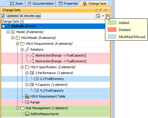
A set of changes made to a server project.
Managing project usages
You can now configure project usages for one or several selected used projects at a time. In only one dialog box you can:
- Control notifying users about new used projects versions
- Add new projects
- Remove used projects
- Start directly using indirectly used projects
- Change the version of a used project
- Review the information of a selected used project.
- Reset changes to a selected used project.
Additionally, in this dialog you can preview any changes applied to your project without closing the dialog.
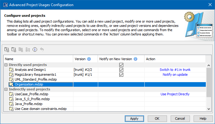
The Advanced Project Usages Configuration dialog.
Hidden packages
Starting with version 19.0, the Hidden Packages model cutting utility is presented. This utility lets you specify which model Packages (and elements within them) should be hidden. Once specified, the non-hidden/public version of the model will be created by cutting/deleting the hidden parts. As a result, the stripped model with only visible model elements is stored in a dedicated branch, which is coupled with the main project branch. You can reuse projects with only visible elements according to your needs.
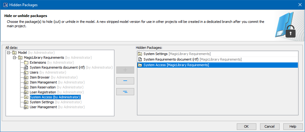
Dialog for selecting packages to hide.
Whenever you need to use a stripped model in other projects, the dedicated branch is suggested by default so that you can select your project to reuse. Also, there is no need to worry about making changes to the main project. Every change affecting the visible (or stripped) project part is synced with a project stored in the dedicated branch. You can do this manually or automatically after committing the changes of the main project to the server. Learn more how to hide packages >>
Disconnected team collaboration
Disconnected teamwork collaboration is dedicated for multiple contractors without the ability to work on the same Teamwork Cloud installation to contribute to projects. This feature allows you to export a server project as a local one, modify it, and import back while updating the server project. This means you can simply save your project locally as a .mdzip file and send this file to another contractor for modification. After the file is sent back, you have the ability to update the same server project from the local project. This life cycle may continue between any amount of contractors. This feature works even when multiple contractors work with separate Teamwork Cloud installations, as well as with Teamwork Server or local installations.
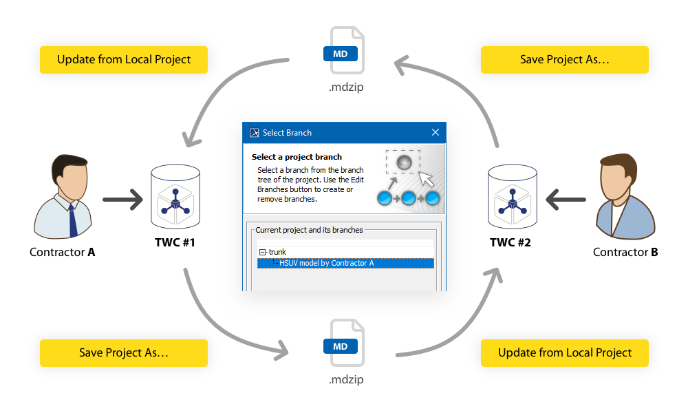
Project development life cycle in a disconnected teamwork environment.
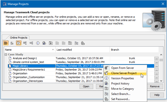
Cloning projects
Now you can clone your latest server project version as a separate project. You can use the project being cloned as a "template" to create a new project or use it as an independent base for new development. IDs of a cloned project and elements are reset automatically. Project permissions are reset as well; the project is available only for a user who has cloned the project. All references to used projects (if there are any) are maintained.
Other enhancements and changes
In the current release, the collaboration working environment has been significantly improved. These include:
- Adding a comment for the package when exporting it to a new server project.
- Displaying a progress bar with data about project changes while retrieving the content of element history. You may stop the collection process if you need to.
- Viewing changes in the model in a particular scope at the element level in the package, as well as in a classifier element in a composed element such as a Block or Requirement.
| Anchor | ||||
|---|---|---|---|---|
|
- Forward compatibility between service packs is provided as of the current version. For example, if you create or update a project with the tool version 19.0 SP2, the project will open in edit mode rather than read-only when it is opened in version 19.0 SP1 (except for the SP2-implemented functionality).
- As of 19.0 version, the Document Modeling Plugin is excluded from Cameo Systems Modeler product. If you want this plugin to assist for modeling the document structure, you can download free the Document Modeling Plugin and install it.
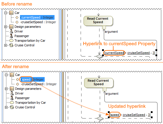
The Comment path is now displayed after dragging
the Comment element from the Model Browser to the diagram pane when enabling the Display Paths on Element Drop option in the Environment Option dialog.
Automatic Behavior Creation (renamed to Behavior Creation Mode) and Type Selection
Mode buttons now work separately for each project. Learn more about Behavior Creation Mode >> Learn more about Type Selection Mode >>
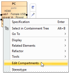
- The Edit Compartments command is now accessible directly from the shortcut menu of the classifier compartments
- (such as Properties, Operations, Receptions, Ports,
- etc). Learn more about displaying or hiding elements in compartments on shapes >>
- You can now specify the custom column and row query in all matrices, when you need to collect
- more than just owned elements. Simply click
") next to Row/Column Scope box in the the Criteria area. Learn more about Criteria area of matrices >>
next to Row/Column Scope box in the the Criteria area. Learn more about Criteria area of matrices >> - Aspect Ratio, a new Diagram Frame symbol property, allows you to choose the appropriate diagram frame format (for example,16:9, A4 Landscape, 4:3 ). Specifying the appropriate diagram frame aspect ratio helps you present diagrams in your PowerPoint or Keynote presentations, PDFs, and so on.
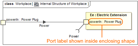
- You are able to specify one more outside label position of a Port. This shows the Port label inside a shape, with the Port created on the shape boundary. Learn how to change the position of port labels >>
- You can choose an existing model element when creating a relation in the relation map. Learn how to decompose an element in the relation map >>
- When creating a new Composite Structure Diagram for a Package, you can specify whether to create a diagram context element automatically or not by selecting an appropriate value for the Diagram Context property in the Project Options dialog. Learn more about Composite Structure Diagram context >>
- As of this version, the Tooltips Style option is located in the Project Options dialog. Learn how to change the tooltips style >>
- You are able to select an additional Show Both or Behavior Name value of the Name Display Mode symbol property for the Call Behavior Action. This allows you to show only the behavior name instead of both if the action name is not specified or the action name matches the behavior name. Learn how to change the name display mode on the Call Behavior Action >>
- When dragging or selecting an image from the Image Library or other resources, you can specify whether to apply an image to the property or to its type in the Project Options dialog > Apply Image To. Learn more about applying images >>
- When specifying a new type for a Activity Parameter Node or Pin in the Activity diagram, you can select the element kind created in the model with a specified name and set as a type.
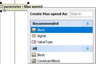
Learn how to specify Pin type >>
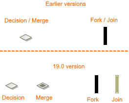
Learn how to specify Activity Parameter Node type >> - The new project option Use different Fork/Join and Decision/Merge notations allows you to draw different notations for the Fork, Join, Decision, and Merge.
- The Note anchored to the diagram frame can now represent the information of the diagram context element (for example, Activity or State Machine). To switch the representation to the diagram information, right-click the Note, and in the shortcut menu clear the selection of Represent Diagram Context.
- You can now define your own documentation server. For that purpose, the new Environment option documentation.server is added to the Path Variables property group. Learn more about working with path variables >>
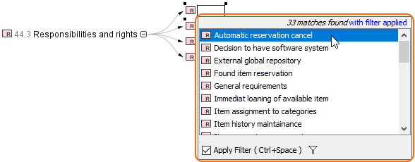
- The filter mechanism includes the following improvements:
- The Exclude Auxiliary Resources replaces the Exclude Used Projects filter option. Learn more about Filter Options >>
- The elements from used projects are included in the search results list by default.
- The new Exclude Auxiliary Resources filter option reduces the search results list by excluding elements contained in auxiliary resources, except elements with the new <<ignoreAuxFilter>> stereotype applied. Learn how to apply stereotype >>
- If you clear the Apply Filter check-box once, your selection is remembered for the next time. - A number of new operations have been added to the built-in operations library.
- Now Mac OS X now supports the mdel:// links and *.mdzip files opening.
- The new documentation layout, including the new home page, is introduced. On the new homepage, you can easily navigate through the menu or simply use the search.
| Anchor | ||||
|---|---|---|---|---|
|
- You can now include the Attached File element to the main template by using #include, #includeSection, $import.include(), and $import.includeSection(). You can also use the Attached File element as a template of $file.create(), $file.silentCreate(), and $file.createAndWait() to generate reports. Learn more about including documents in generated reports >>
- The DOCX template can now dynamically import the content of other DOCX documents by using $import.include() and $import.includeSection() at runtime, as an alternative to existing RTF, HTML, and text template support. Learn how to import DOCX documents to generate reports >>
- There is now a more convenient, flexible way to generate reports through a command line prompt by specifying element IDs of single or multiple elements in Cameo Systems Modeler projects as the report scope. Learn more about specifying element IDs via command line prompt >>
- The dialog tool API is now equipped with a select method to create more customized Selection dialog boxes. You can select elements during runtime through the user interface. Learn how to create a customized Selection dialog through Dialog tool API >>
| Anchor | ||||
|---|---|---|---|---|
|
- The Personal edition is discontinued for all modeling tools.
- For business process modeling, only the Cameo Business Modeler plugin is supported. The development of Cameo Business Modeler tool is discontinued.
- For Cameo Enterprise Architecture, only the Enterprise edition remains. Support of other editions is discontinued. We assure you that the modeling features will not be affected by this change.
- Integration of Eclipse, Rational Application Developer (RAD), openArchitectureWare (oAW), and AndroMDA are no longer supported.
- Neither Struts nor Web diagrams are supported in the modeling tool any longer.
Development of the Cameo SOA+ plugin is discontinued. However, you will still be able to load projects created in earlier versions with this plugin in your modeling tool. The maintenance of the SoaML profile is continued and SoaML diagrams have been moved to the SoaML profile resource.
| Content block | |||||||||||||||
|---|---|---|---|---|---|---|---|---|---|---|---|---|---|---|---|
| |||||||||||||||
The latest Cameo Systems Modeler Documentation Anchor | resources | resources |
Panel | |